Around 2004 I developed a few protoype microphones enhanced to also offer proximity detection. The microphone could adjust it’s amplitude and bass response based on the proximity of the person using it. This would lessen the variable results users experience when holding a microphone too close or too far. Moreover, with proximity or its derivative mapped to a combination of digital effects, the microphone could offer a wealth expressive possibilities for a musician or singer.
Automatic Gain Control (AGC) circuits are also often used to address inconsistencies in microphone use. AGC uses only the audio signal when adjusting audio gain. If the audio signal is low, the gain is boosted. If the audio signal is high, the gain is cut. However, proximity detection offers advantages over AGC:
- If a person chooses to speak loudly or softly for effect, AGC minimizes this effect.
- AGC cannot distinguish between somebody pausing and somebody far away from the microphone. Therefore, AGC increases gain during pauses. This is called “pumping.” Pumping can be very disturbing to listeners, as they hear background noise steadily rising during pauses.
- AGC circuits either have to delay their audio signal coming out or, more commonly, they adjust audio gain “on the fly.” Delaying the audio signal coming out can be confusing to listeners and users and is not practical in musical applications. Adjusting on the fly means that the gain adjustment is always slightly delayed. As a result, each time a person using a microphone takes a breath, the gain increases and the audience hears the “pumping.” When the user again begins to talk, the amplifier is disturbingly loud for a brief moment before the circuitry compensates.
- Microphones lose bass response as a function of distance. It would be difficult for an AGC circuit to detect this loss and compensate. However, a microphone with proximity detection could compensate for this easily.
Prototype I: Analog Electronics and Capacitive Sensing
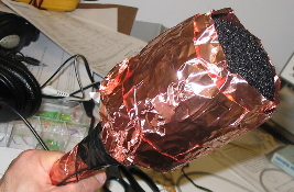
The first prototype used capacitive sensing and analog electronics to offset the gain of the microphone in inverse proportion to its distance from the user. The intention was that the microphone would then be more transparent to the user and have a more intuitive interface.
This prototype ran on 2 9V batteries and could amplify the audio gain up to 8 decibels. I tested the prototype by having a test subject hold an unmodified microphone in the same hand as the prototype, then having the subject move both microphones toward and away from their mouth while continually talking as shown above. Listen to the difference between the recorded audio of the two microphones:
Prototype II: Digital Signal Processing and Ultrasonic Sensing

Prototype I served as a good proof of concept, but the sensing was finicky and the analog electronics limited flexibility in how the system could be expanded. Ultrasonic sensing with multiple sensors could be a more robust approach and also give more sensor information. Large objects in the sensing environment or tilt could more accurately be accounted for.
Moving from an analog environment to a digital signal processing environment offers greater flexibility in how the system could be used. With software changes alone, it would be possible to change the system to adjust not just for bass response and equalization but instead to map the values from the ultrasonic sensors to various musical effects. Through software mapping, the microphone could become a new type of music controller.
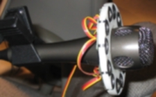
Prototype II used 6 pairs of Devantech SRF10 ultrasonic rangefinders mounted to a plastic structure I designed in Blender and printed on a 3D printer. The rangefinders outlined the circumference of the microphone. Each pair consisted of one transmitter, one receiver, and a microcontroller. The rangefinders were slaves on an I2C bus, hosted by an Analog Devices ADSP2181 DSP development board. The DSP chip calculated overall distance measurement by reading the distance measurements of each of the pairs of rangefinders, applying a moving average filter, and adjusting the audio gain accordingly.
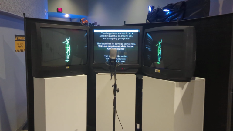
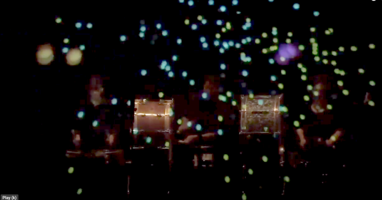
To test Prototype II, I attached the microphone to a stand and had a test subject move toward it and away from it while speaking continuously. I then recorded a stereo signal into a computer. The left channel was a direct feed of the unaltered signal from the microphone. The right channel was amplified variably by the DSP development board and rangefinders
The video of this test shows the real-time recorded signal of both channels for comparison. In addition, the laptop on the left shows two bars. The left bar shows the real-time distance measurement as reported by the DSP chip. The right bar shows the gain adjustment, which was a function of the square of the distance.